Power and RMS values
 The power p converted in a resistor (ie the rate of conversion of electrical energy to heat) is The power p converted in a resistor (ie the rate of conversion of electrical energy to heat) is
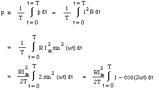
We use lower case p(t) because this is the expression for the instantaneous power at time t. Usually, we are interested in the mean power delivered, which is normally written P. P is the total energy converted in one cycle, divided by the period T of the cycle, so:
|
In the last line, we have used a standard trigonometrical identity that cos(2A) = 1 - 2 sin2A. Now the sinusoidal term averages to zero over any number of complete cycles, so the integral is simple and we obtain
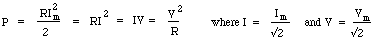
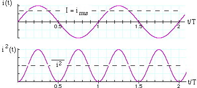
This last set of equations are useful because they are exactly those normally used for a resistor in DC electricity. However, one must remember that P is the average power, and V = Vm/√2 and I= Im/√2. Looking at the integral above, and dividing by R, we see that I is equal to the square root of the mean value of i2, so I is called the root-mean-square or RMS value. Similarly, V = Vm/√2 ~ 0.71*Vm is the RMS value of the voltage.
When talking of AC, RMS values are so commonly used that, unless otherwise stated, you may assume that RMS values are intended*. For instance, normal domestic AC in Australia is 240 Volts AC with frequency 50 Hz. The RMS voltage is 240 volts, so the peak value Vm= V.√2 = 340 volts. So the active wire goes from +340 volts to -340 volts and back again 50 times per second. (This is the answer to the teaser question at the top of the page: rectification of the 240 V mains can give both + 340 Vdc and -340 Vdc.)
* An exception: manufacturers and sellers of HiFi equipment sometimes use peak values rather than RMS values, which makes the equipment seem more powerful than it is.
Power in a resistor. In a resistor R, the peak power (achieved instantaneously 100 times per second for 50 Hz AC) is Vm2/R = im2*R. As discussed above, the voltage, current and so the power pass through zero volts 100 times per second, so the average power is less than this. The average is exactly as shown above: P = Vm2/2R = V2/R.
Power in inductors and capacitors. In ideal inductors and capacitors, a sinusoidal current produces voltages that are respecively 90° ahead and behind the phase of the current. So if i = Imsin wt, the voltages across the inductor and capacitor are Vmcos wt and -Vmcos wt respectively. Now the integral of cos*sin over a whole number of cycles is zero. Consequently, ideal inductors and capacitors do not, on average, take power from the circuit.
Three phase AC
Single phase AC has the advantage that it only requires 2 wires. Its disadvantage is seen in the graph at the top of this page: twice every cycle V goes to zero. If you connect a phototransistor circuit to an oscilloscope, you will see that fluorescent lights turn off 100 times per second (or 120, if you are on 60 Hz supply). What if you need a more even supply of electricity? One can store energy in capacitors, of course, but with high power circuits this would require big, expensive capacitors. What to do?An AC generator may have more than one coil. If it has three coils, mounted at relative angles of 120°, then it will produce three sinusoidal emfs with relative phases of 120°, as shown in the upper figure at right. The power delivered to a resistive load by each of these is proportional to V2. The sum of the three V2 terms is a constant. We saw above that the average of V2 is half the peak value, so this constant is 1.5 times the peak amplitude for any one circuit, as is shown in the lower figure at right.
Do you need four wires? In principle, no. The sum of the three V terms is zero so, provided that the loads on each phase are identical, the currents drawn from the three lines add to zero. In practice, the current in the neutral wire is usually not quite zero. Further, it should be the same guage as the other wires because, if one of the loads were to fail and form an open circuit, the neutral would carry a current similar to that in the remaining two loads.
| The voltage (top) and square of the voltage (bottom) in the three active lines of 3 phase supply.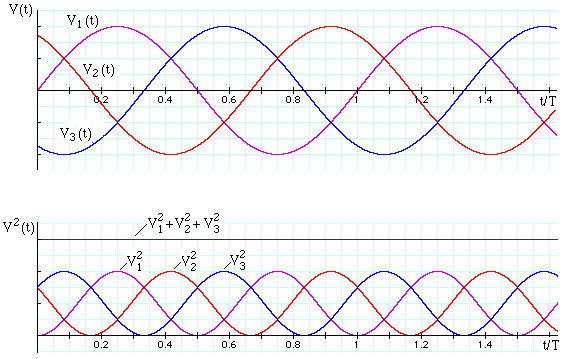 |